Home » RGB LED Solderless Kit » Playstation 2 SG – Solderless Kit
Playstation 2 SG – Solderless Kit

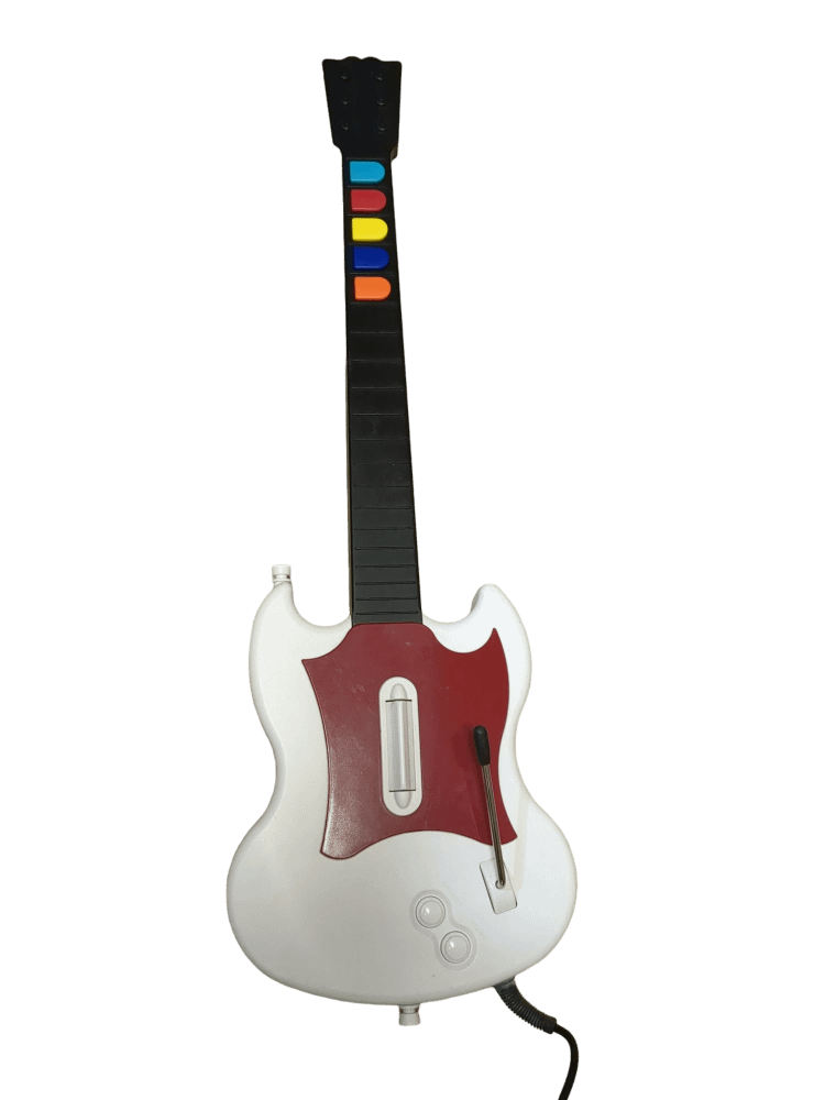
PS2 SG RGB Solderless Kit
Note on text/pictures: This guide uses color coded steps and images. For example, instructions that have a green dot next to them will relate to green shapes in the accompanying images (usually an arrow). Same for all other colors.
Note on Component Bag: You will have leftover components after completing the mod; this is normal.
PS2 SG controllers come in varying colors, but the process to mod them is the same!
Tools Needed/Parts Included
Tools needed (not included):
- Wire Strippers (24 AWG recommended)
- Flush Cutters
- Screwdriver and Bits (T6, T10, PH1, PH2, 1/16th inch flathead)
Purchase Links: Wire Strippers Screwdriver + Bits Flush Cutters
Parts Included with the kit:
- Component Bag
- USB-C Cable
- 3x JST Cables (twisted)
- 5x 3D Printed Frets (translucent)
- Zeroboard SL
- Fretboard SL
- 2x 3-Pin Jumper Cable
- 2x 3-Pin Splicer
Opening the Controller
Flip the controller over so the Red Octane sticker on the back of the body is visible. Remove the following screws
- Rear body shell - 11x T10 screws (remember the one under the Warranty sticker)
- Rear neck shell - 5x T10 screws
- Ensure that all of the screws are removed, and open the shell. I recommend starting to pry gently from the opening near the neck connector.
Once the shell begins to open, slowly move down the rest of the shell until it pops open completely.
- Repeat this process for the neck, using the opening at the neck connector and working towards the headstock.
If the shell seems to gets stuck, DO NOT FORCE IT. Check to make sure you have removed all of the screws before continuing to pry the shell.
Cutting the stock wires
We will be making cuts on some of the stock wires in the shell to prepare them for the new boards. Use your flush cutters for this and follow the instructions carefully!
- Cut the wires connecting the start/select board and whammy to the mainboard connector. Cut as close as possible to the mainboard to leave plenty of wire to run to the new strumboard.
Removing stock boards
Now its time to remove the stock boards that will be replaced with the new boards included in the kit.
- Remove the 4x PH1 screws on the stock strumboard. Remove the stock strumboard and the PS2 cable connected to it.
Keep the start/select board and whammy in the body.
- Remove the 2x PH1 screws on the stock fretboard.
Preparing wires for the Zeroboard SL
We will now need to prepare the wires for the new strumboard. We’re going to use the 22 AWG slot of our wire strippers to do so.
- Separate the 3 or 4 wires of the ribbon cable coming from the start/select board. Strip away about 1/3 of an inch (1 cm) of sheathing from the wire.
- Separate the 3 wires of the ribbon cable coming from the whammy bar. Strip away about 1/3 of an inch (1 cm) of sheathing from the wire.
-
Insert all 3 of the JST cables (twisted) into the 3 JST connectors on the Zeroboard labelled:
RGB LED
GND/ORANGE/BLUE
YELLOW/RED/GREEN
How to use the splicers and screw terminals
Here’s how to use the grey and orange splicers just in case the stock wires do not reach the new Zeroboard. It is recommended to twist the exposed wires with your finger to make them easier to insert.
- Lift the orange lever to open the slot on the splicer.
- Insert the wire into the slot, making sure that the exposed metal of the wire is touching the metal in the slot, and not the sheathe the wire. Snap the orange lever down to engage the clamp on the wire.
Here’s how to use the green screw terminals on the Zeroboard to connect the stock boards and whammy.
- Using your 1/16th inch flathead bit, turn the screw counter-clockwise to open the terminal slot.
- Insert the expose metal of the wire into the slot, then rotate the screw clockwise to clamp it down onto the wire.
Make sure that none of the exposed metal of the wires are touching each other; this may cause bridging issues.
Installing the Zeroboard SL
Now we will connect the remaining stock boards to the new strumboard.
- Using 4 screws from the component bag and a PH1 bit, install the Zeroboard SL onto the standoffs that the old strumboard sat on. Make sure the twisted JST wires are not caught under the Zeroboard. The stock screws can be used if you want!
Connect the 3 wires coming from the start/select board into the section of the Zeroboard SL labelled SEL/START/GND.
-
J2 Wire on stock board to START on Zeroboard
Center Wire on stock board to GND on Zeroboard
Left Wire on stock board to SEL on Zeroboard
-
Whammy bar:
Center wire on whammy to ADC on Zeroboard
The remaining 2 wires can go to either two remaining open terminals, order does not matter.
Installing the Fretboard SL
Next, we will install the new mechanical fretboard and translucent frets.
- Connect the other ends of the twisted JST wires from the Zeroboard to the corresponding connectors on the new Fretboard. Make sure these connections are fully inserted into the connectors. (Refer to the example image)
- Remove the stock frets and replace them with the translucent 3D printed frets provided in the kit. These frets must be used even if you do not want to use LEDs; the stock frets will not fit with the new Fretboard.
- Using 2 screws from the component bag and a PH1 bit, install the new Fretboard onto the standoffs that the old fretboard sat on. Make sure the twisted JST wires are not caught under the board or screws.
Coil up the excess wire and use a piece of tape to hold it down to the neck shell. Make sure the cable is clear of any plastic standoffs, as this can pinch and even break the cable if they are in the way when you reassemble the shell.
Installing the tilt sensors and USB cable
Now its time to install the tilt sensors and USB-C cable, as well as test all of our connections!
- Insert the tilt sensors into the slot as pictured. Bend the sensors to the left side and down towards the bottom of the board until they sit at about a 45 degree angle. We will fine tune the tilt angle shortly.
- Connect the USB-C cable into the USB-C port on the Zeroboard. I recommend looping the cable once near the USB-C end and seating it under the edge of the start/select board. This way, if the cable was yanked on, it wouldn't easily disconnect from the Zeroboard!
Programming the guitar and calibrating whammy
If you haven’t already, download the programming tool from this link:
RCM Programming Tool
- Check your Zeroboard SL to determine if it is the original version or version 1.1. The 1.1 version will have "v1.1" on the board, while the original will not have any version number. This will determine which preset gets applied in the next step.
- Connect the guitar to a USB port directly connected to your PC (not a USB hub). Open the tool and select Zeroboard SL (Solderless Kit) for Device Type, and Zeroboard SL - Default if the board is original, or Zeroboard SL - Default v1.1 for the v1.1 board version under Device Variant. Then, click Erase and Configure.
- Once the status bar is at 100%, click Configure. Click the arrow on the Whammy section to expand it. Click Calibrate, then with the whammy bar untouched, click Next. While holding the whammy all the way down, click Next again. Let the whammy go, and then push down on it very slightly and click Next again. Your whammy bar should now be calibrated!
If you’d like to use the default RGB LED fret colors, click Save Settings and you’re done! If not, you can expand all of the different frets and set their pressed and released color to whatever you’d like!
Tuning the tilt angle
- Open your Start Menu, type in "joy.cpl", and hit Enter.
- Select the guitar controller and click Properties.
- Click the Test tab.
- Slowly tilt the guitar neck upwards until the Z Rotation axis goes to 100%. If it hits 100% at too low of an angle for your tastes, physically angle the sensors down towards the bottom of the Zeroboard, creating a more aggressive tilt angle. If it activates too high, then bring the sensors back up closer to horizontal.
Test all the other buttons and make sure that each one corresponds to a button lighting up on the Test tab!
Finishing Up
You’re almost done! Once you have ensured that each input works and that the tilt angle is where you want it to be, we can close up the guitar!
Make sure none of the wires are in the way of any plastic standoffs, as this will damage them when closing the shell. I would recommend taping down the wires to ensure they are out of the way.
With the front body and neck shell facing down, put the rear neck shell onto the front neck shell. You will need to apply pressure to close the shell. If you feel like part of the shell will not snap into place, open it up and double check that there is nothing blocking the standoffs. Repeat for the body shell.
After both sides are clamped down, install all of the screws you removed earlier:
- Rear neck shell - 5x PH1 screws
- Body shell - 11x PH1 screws
Start playing!
Experiencing any issues? Reach out to me: support@RetroCultMods.com

