
Home » Revival Kit for Guitar Hero Controllers » Playstation 2 Mayflash – Revival Kit
Playstation 2 Mayflash – Revival Kit
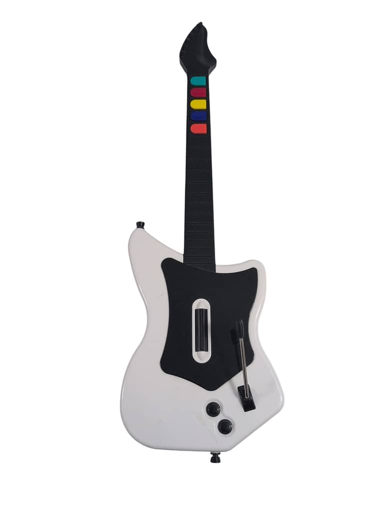
PS2 Mayflash Revival Solderless Kit
Note on text/pictures: This guide uses color coded steps and images. For example, instructions that have a green dot next to them will relate to green shapes in the accompanying images (usually an arrow). Same for all other colors.
Note on Component Bag: You will have leftover components after completing the mod; this is normal.
Tools Needed/Parts Included
Tools needed (not included):
- Screwdriver with PH1, T10, and T6 bits
- Flush cutters
Purchase Link: Screwdriver + Bits
Parts Included with the kit:
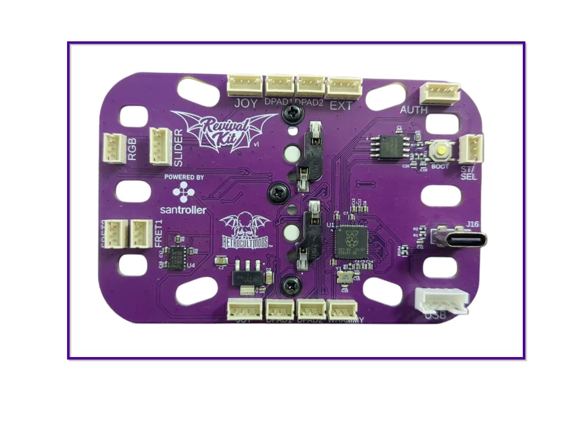
- Revival Kit Zeroboard (Strumboard)
- Revival Kit Fretboard
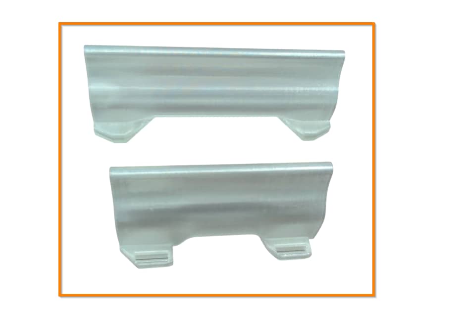
- 3D Printed Translucent Strumbar (different for each model)
- 5x 3D Printed Translucent Frets
- Replacement boards (different for each model)
- Detachable USB-C Board and components
- New Whammy Assembly
- Switch Puller
- Color Coded Wires and Breakaway Cable (different for each model)
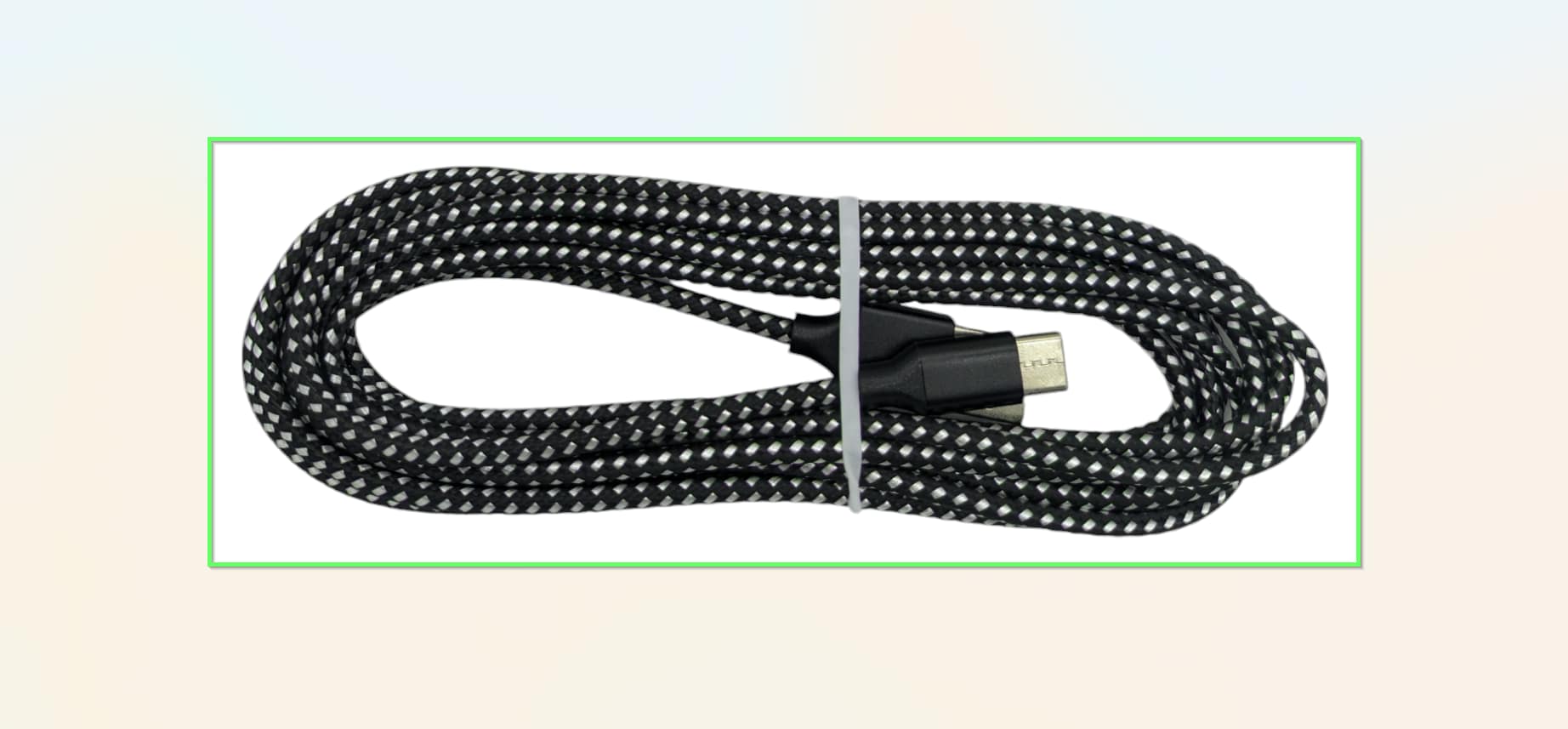
- 10 foot nylon braided USB-A to USB-C cable
- Tube of lubricant
Opening the Controller
Flip the controller over so the Red Octane sticker on the back of the body is visible. Remove the following screws
- Rear body shell - 12x PH1 screws (remember the one under the Warranty sticker)
- Rear neck shell - 6x PH1 screws
- Ensure that all of the screws are removed, and open the shell. I recommend starting to pry gently from the opening near the neck connector.
Once the shell begins to open, slowly move down the rest of the shell until it pops open completely.
- Repeat this process for the neck, using the opening at the neck connector and working towards the headstock.
If the shell seems to gets stuck, DO NOT FORCE IT. Check to make sure you have removed all of the screws before continuing to pry the shell.
Removing stock boards
- Before separating the body shells, wiggle the ribbon cable that connects to the battery terminal back and forth until it breaks away.
Now its time to remove the stock boards that will be replaced with the new boards included in the kit.
- Remove the 4x PH1 screws on the stock strumboard.
- Remove the 2x PH1 screws on the stock start/select.
- Remove the 2x PH1 screws on the stock whammy potentiometer bracket.
Remove all boards and all connected components from the body. Remove the whammy potentiometer bracket as well.
- Pull the stock whammy potentiometer out of its bracket. Do this by pulling up and pulling it away from the whammy bar.
Installing the Revival Kit Zeroboard (Strumboard)
With the stock boards removed, we can now install the new strumboard.
- Detach the strumcaps with the plus shaped cutout from the 3D printed component piece.
- Place the new strumboard on top of the black brackets, then screw in the new strumboard. If the stock screws are stripped, you can use the replacement Long Screws provided in the kit. Make sure each screw is snug, but do not over-tighten them, or you may scratch away the soldermask of the new strumboard!
Installing the new Start/Select board
Now its time to install our new Start/Select board.
Gather the new Start/Select board (labelled 1A) and 2 Long Screws.
- Swap the silicone domes on the stock start/select board onto the new board.
- Secure the new Start/Select board in the place of the stock Start/Select board, positioned with the white connector closest to the Strumboard. The original screws will likely be too small to cover the slots of the new board, so the provided screws can be used instead.
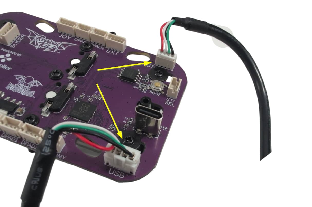
- Connect one end of the Red Wire into the white connector on the new Start/Select board. Connect the other end of the Red Wire into the white ST/SEL connector on the Strumboard.
Installing the Revival Kit Fretboard
Now its time to install the new RGB Mechanical Fretboard.
Gather the Revival Kit Fretboard, Translucent Frets, 3 White Wires, and 2 Long Screws.
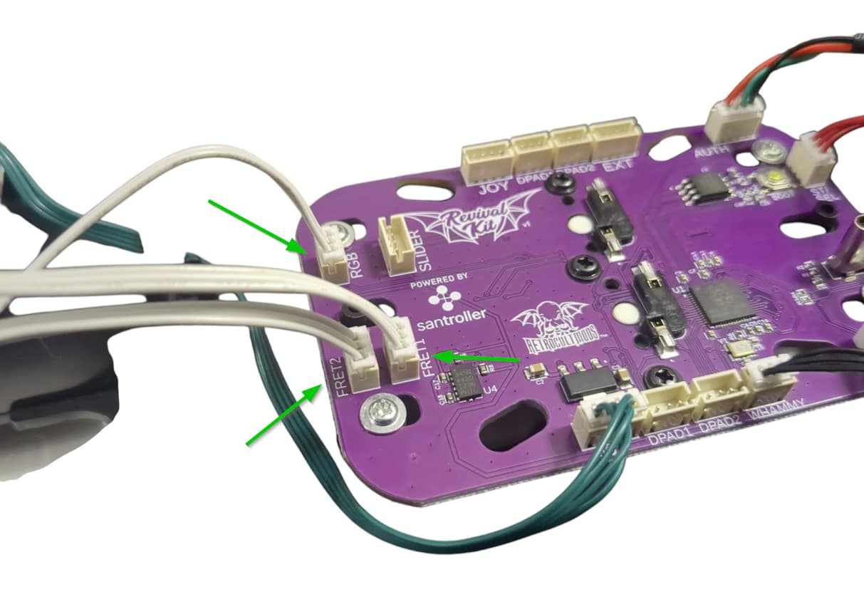
- Connect one end of each of the White Wires into the RGB, FRET1, and FRET2 connectors on the Fretboard. Connect the other end of each White Wire to the corresponding RGB, FRET1, and FRET2 connectors on the Strumboard. I recommend doing one wire at a time to prevent mixing them up.
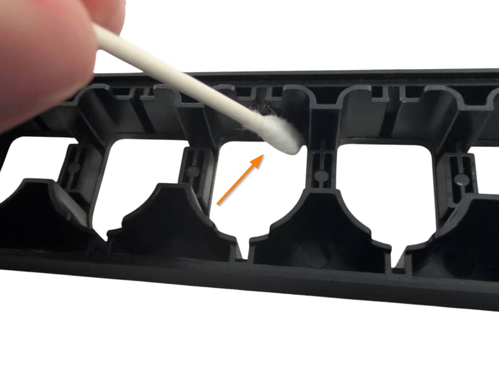
- Remove the stock silicone pad and frets if they are still in the fret slots. Wipe the inside of the fret slots clean if they are dirty. Then apply a small amount of lubricant to your finger or a qtip and lightly coat the inside of the fret slots with lubricant. Make sure to wipe away any excess lubricant that my have spilled to the front of the neck shell!
- Insert the new Translucent Frets into the fret slots.
- Place the new Fretboard onto the screw standoffs that the stock fretboard used to sit on (the red switches and white connectors should be facing down towards the Translucent Frets. Use 2 Long Screws to secure the new Fretboard.
- Route the White Wires through the neck and down through the body. Make sure they are clear of any screw standoffs so they are not damaged when reinstalling the neck shell.
Installing the new Whammy assembly
Installing the new whammy assembly is up next.
- Gather your new whammy potentiometer, the circular whammy cap, and the potentiometer holder.
- Push the whammy cap onto the new potentiometer.
- Press the new potentiometer into the potentiometer holder.
- Remove the small black rubber piece from the center of the whammy slot. Use your flush cutters to remove the bottom part of the whammy slot. Snip both sides, then wiggle the plastic back and forth until it snaps away.
- Push the top of the whammy cap into the whammy bar.
- Push the potentiometer holder down, aligning the slot in the holder to the outer body shell.
- Make sure everything is seated securely. There may be a very small amount of play in the bracket and cap!
Installing the Breakaway cable
Next we’ll set up the USB-C and Authentication breakaway cable.
- Plug the larger white connector on the other end of the cable into the USB connector on the new strumboard. Connect the smaller one into AUTH.
Press the cable down into the space between the start/select board and whammy shell cutouts; make sure it is not in the way of any screw standoffs.
Finishing Up
You’re almost done! Once you have ensured that each input works and that the tilt angle is where you want it to be, we can close up the guitar!
Make sure none of the wires are in the way of any plastic standoffs, as this will damage them when closing the shell. I would recommend taping down the wires to ensure they are out of the way.
With the front body and neck shell facing down, put the rear neck shell onto the front neck shell. You will need to apply pressure to close the shell. If you feel like part of the shell will not snap into place, open it up and double check that there is nothing blocking the standoffs. Repeat for the body shell.
After both sides are clamped down, install all of the screws you removed earlier:
- Rear neck shell - 5x PH1 screws
- Body shell - 11x PH1 screws
Start playing!
Experiencing any issues? Reach out to me: support@RetroCultMods.com
