
Home » Revival Kit for Guitar Hero Controllers » Playstation 2 Kramer – Revival Kit
Playstation 2 Kramer – Revival Kit

PS2 Kramer Revival Solderless Kit
Note on text/pictures: This guide uses color coded steps and images. For example, instructions that have a green dot next to them will relate to green shapes in the accompanying images (usually an arrow). Same for all other colors.
Note on Component Bag: You will have leftover components after completing the mod; this is normal.
Tools Needed/Parts Included
Tools needed (not included):
- Screwdriver with PH1, T10, and T6 bits
- Flush cutters
Purchase Link: Screwdriver + Bits
Parts Included with the kit:
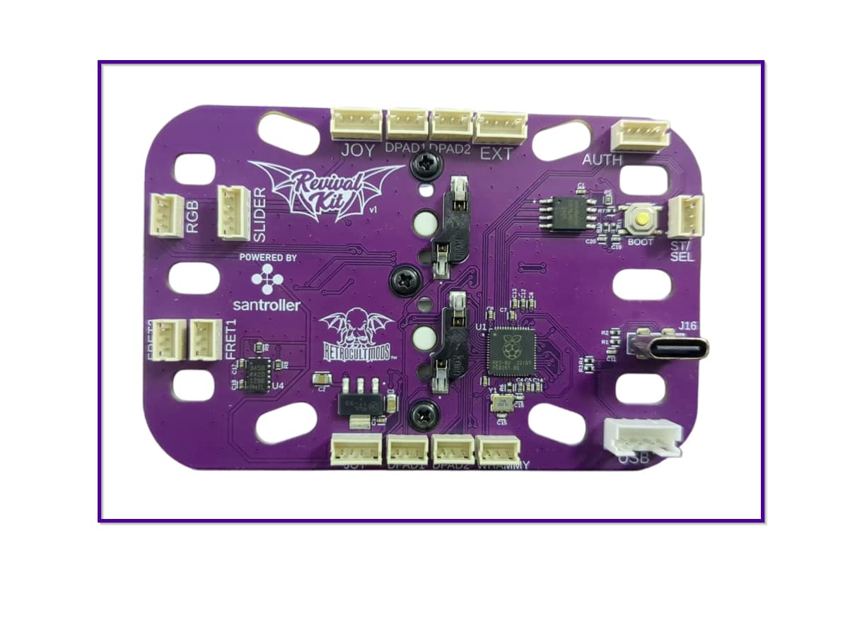
- Revival Kit Zeroboard (Strumboard)
- Revival Kit Fretboard
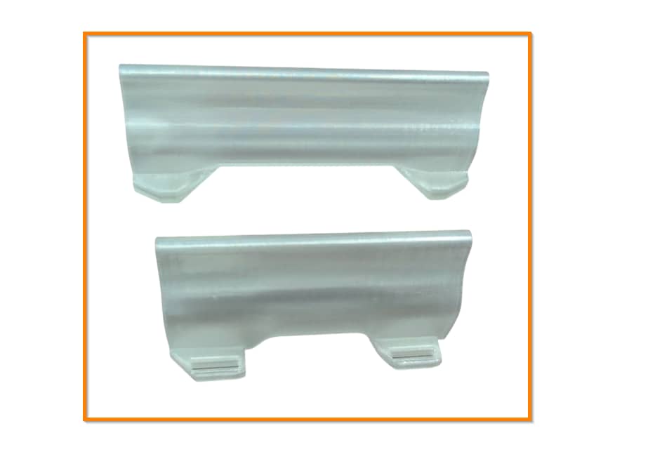
- 3D Printed Translucent Strumbar (different for each model)
- 5x 3D Printed Translucent Frets
- Replacement boards (different for each model)
- Detachable USB-C Board and components
- New Whammy Assembly
- Switch Puller
- Color Coded Wires and Auth Cable (different for each model)
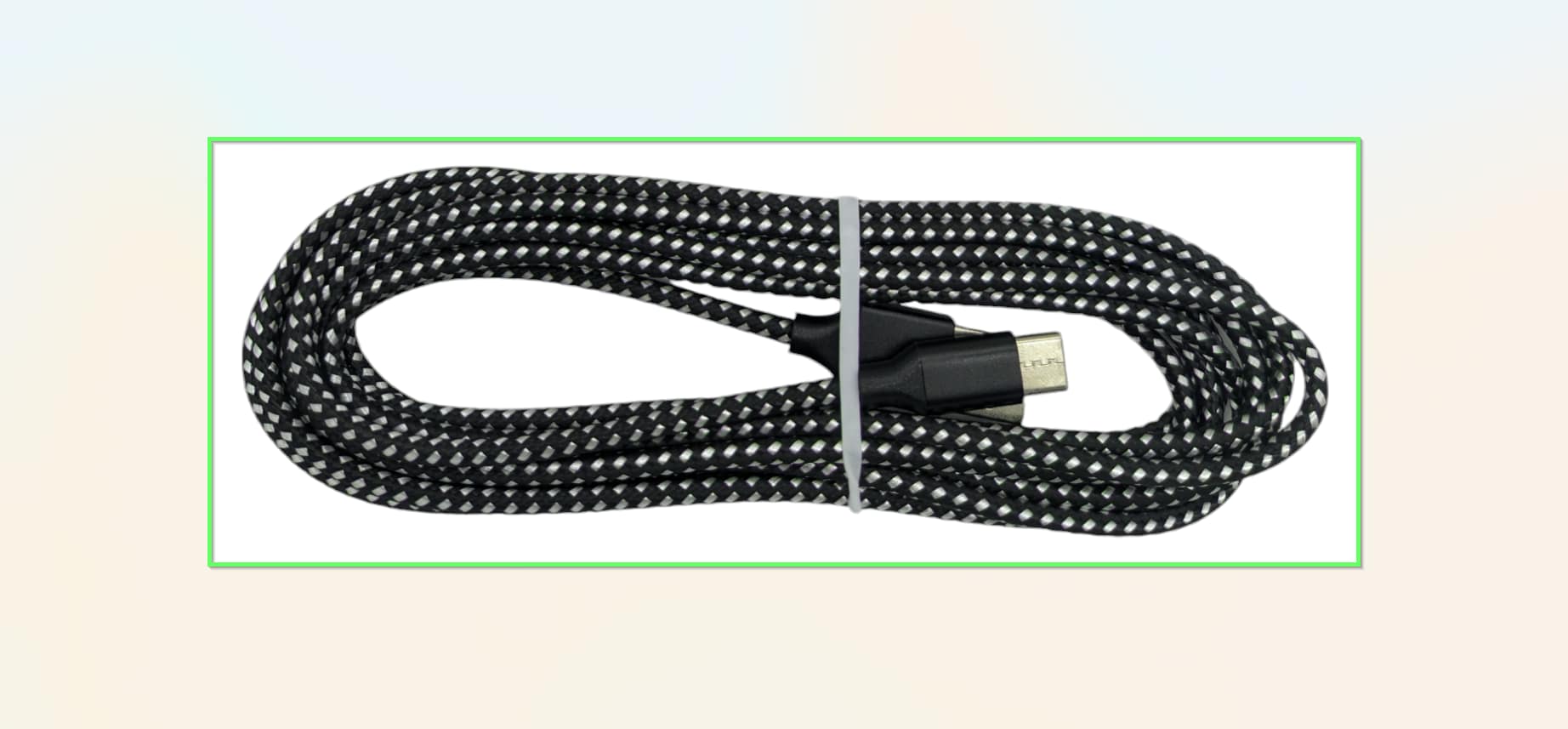
- 10 foot nylon braided USB-A to USB-C cable
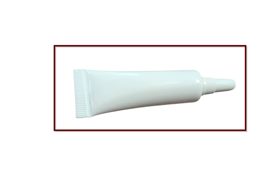
- Tube of lubricant
Opening the Controller
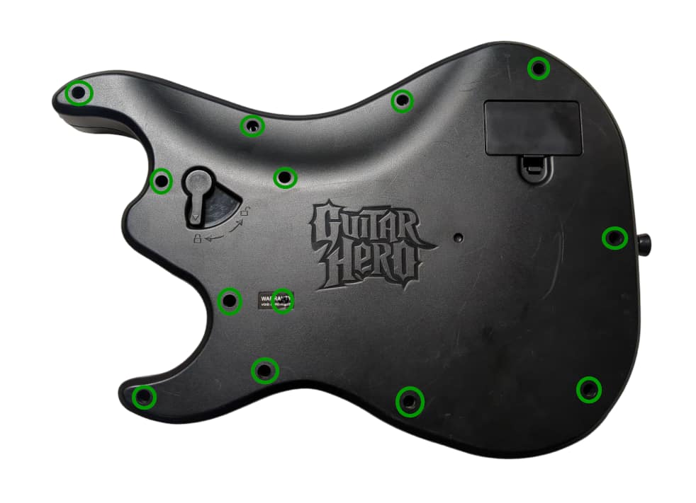
Flip the controller over so the Guitar Hero logo on the back of the body is visible. Remove the neck from the body. Remove the following screws:
- Rear body shell - 13x T10 screws (remember the one under the Warranty sticker)
- Rear neck shell - 8x T10 screws
- Ensure that all of the screws are removed, and open the shell. I recommend starting to pry gently from the opening near the neck connector.
Once the shell begins to open, slowly move down the rest of the shell until it pops open completely.
- Remove the battery board by unscrewing the 2x PH1 screws holding it down
- Repeat this process for the neck, using the opening at the neck connector and working towards the headstock.
If the shell seems to gets stuck, DO NOT FORCE IT. Check to make sure you have removed all of the screws before continuing to pry the shell.
Removing stock boards
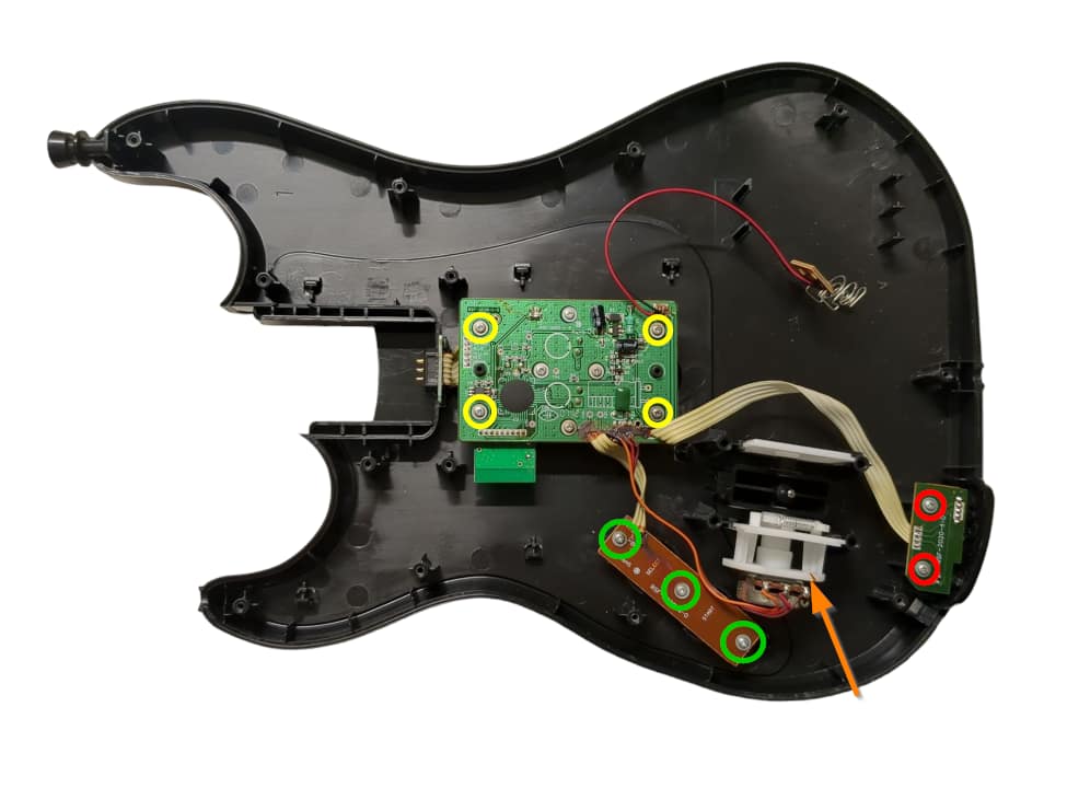
Now its time to remove the stock boards that will be replaced with the new boards included in the kit. For most models these boards will use PH1 screws, but some use T6.
- Remove the 2 screws on the RJ11 (foot pedal) port.
- Remove the 4 screws on the stock strumboard.
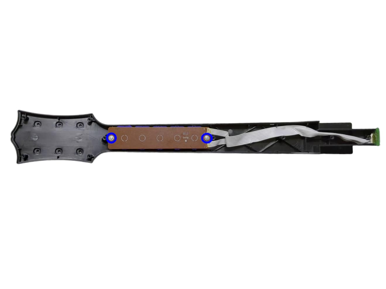
- Remove the 2 screws on the stock fretboard.
- Remove the 3 screws on the stock start/select board.
- Remove the stock whammy component from its slot.
Remove all internal boards and the stock whammy component and store them or dispose of them. We should now be left with an empty shell.
Prepping the new Strumbar
Before installing the new Strumboard, we need to transfer some pieces of the stock strumbar over to the new one:
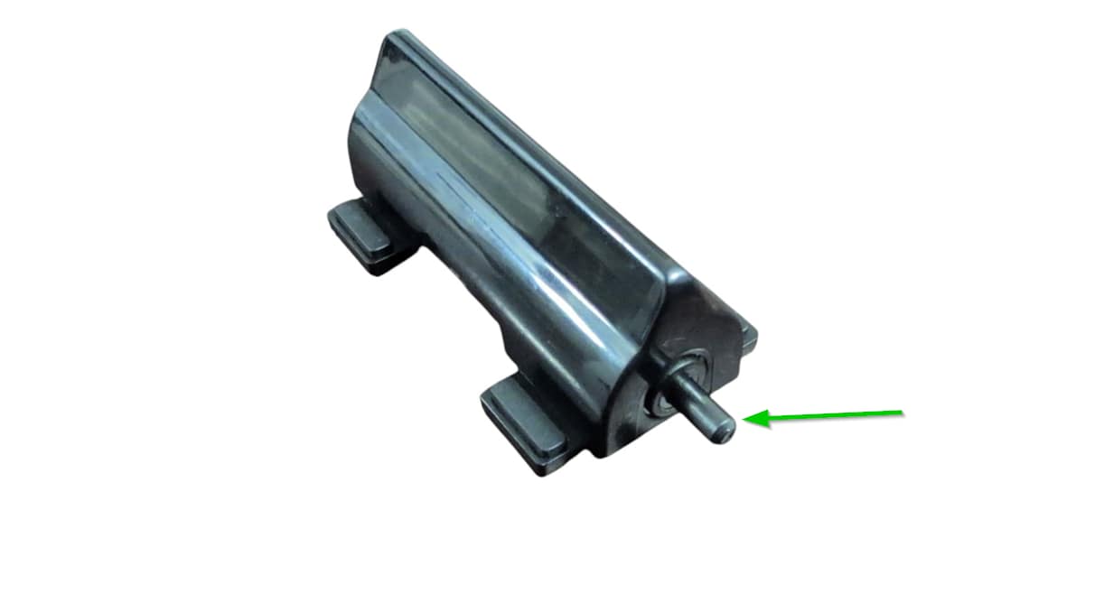
- Remove the metal strumrod by pulling it out of the stock strumbar.
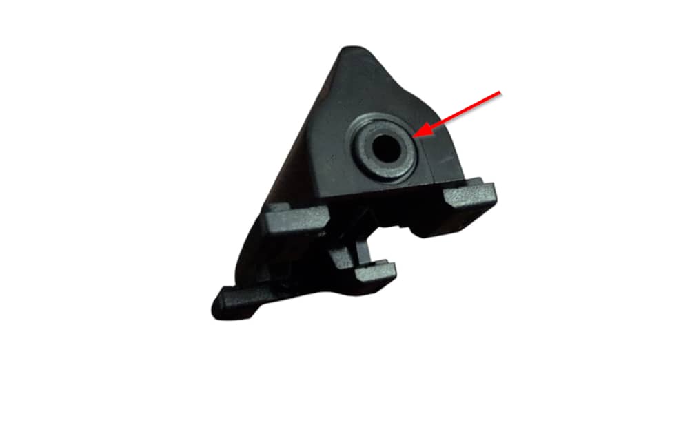
- Remove both of the circular spacers on each end of the strumbar. You can easily remove these by pushing them out with your finger from the inside of the strumbar.
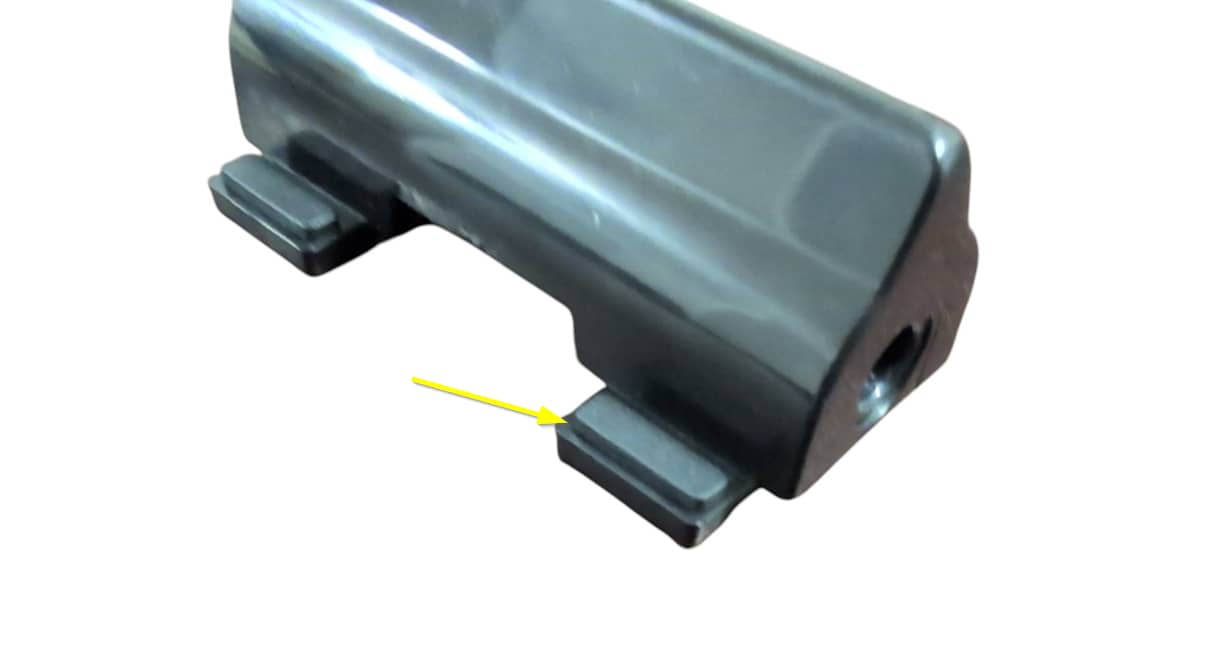
- Remove the four rubber pads on each foot of the strumbar. These can be lifted straight out of their slots.
-
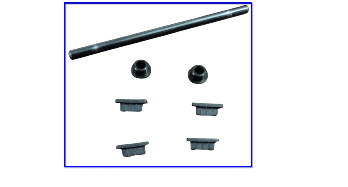
Make sure you have all the stock parts you need:
1x Metal strumrod
2x Circular spacers
4x Rubber pads
- Find the white tube of lubricant and apply a very small amount on each end of the metal strumrod, where it makes contacts with the circular spacers. Use for finger or a qtip to spread the lubricant out; we want only a thin layer of lubricant on the ends of the strumrod!
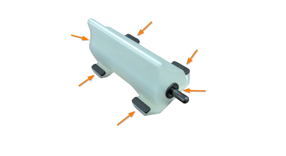
- Put all of these parts into the new strumbar, in the same places as the stock strumbar. Insert the rubber pads into the slots in each of the feet of the new strumbar, insert the spacers into the circular cutouts on each end of the new strumbar, then insert the metal strumrod through the spacers.
-
If the strumbar slides up and down the metal rod too much for your liking, then you can install the wide, thin spacers included on the end of the component piece to fill in the gap. Place these under the stock strumbar spacers. You may need to stack multiple on each end to get your desired tolerance!
If the strumbar does not appear to reach the strum switches, then remove the four rubber feet from the new strumbar.
Installing the Revival Kit Zeroboard (Strumboard)
With the stock boards removed, we can now install the new strumbar and strumboard.
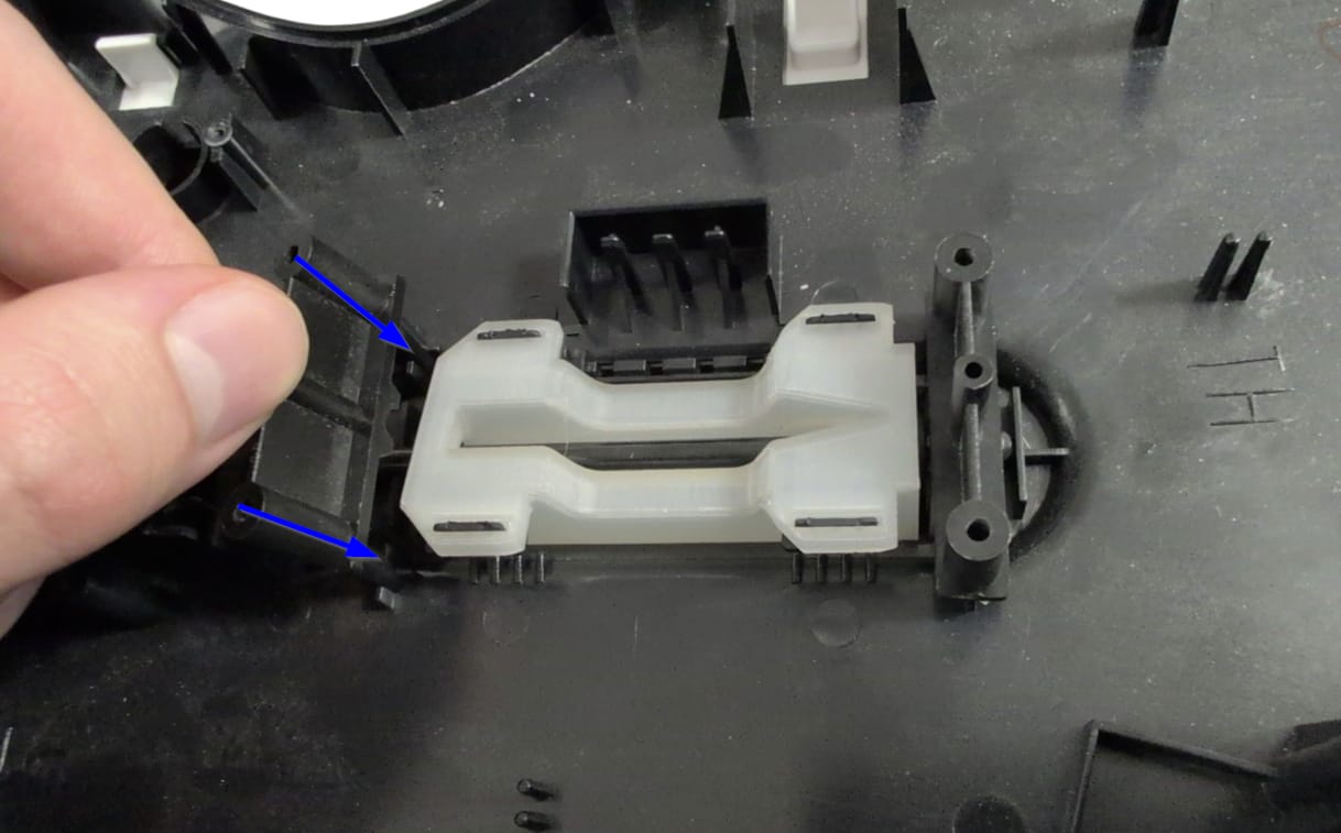
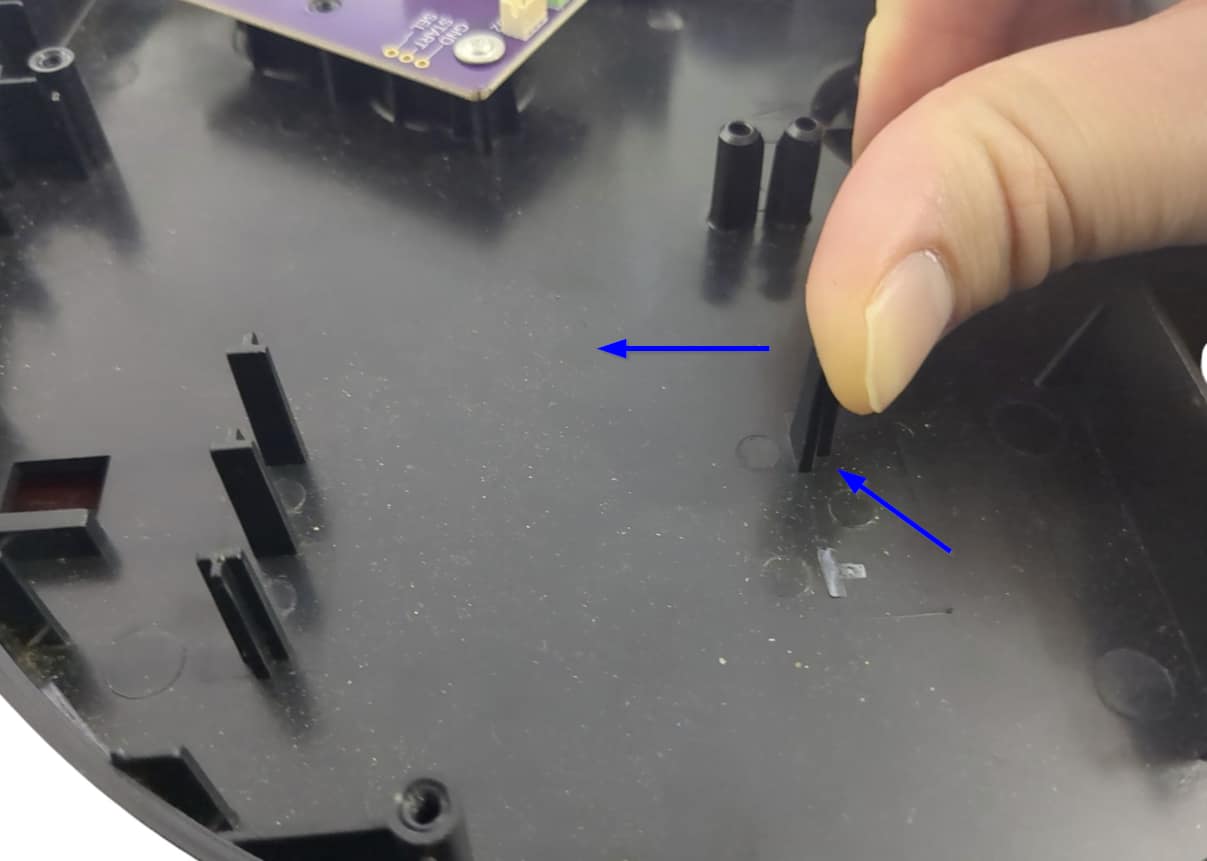
- Remove the black brackets on either side of the stock strumbar.
- Slide the metal rod into the new strumbar. Then place the new stumbar into the slot that the stock strumbar sat in. Put the black brackets back into place.
- Place the new strumboard on top of the black brackets, then screw in the new strumboard. If the stock screws are stripped, you can use the replacement Long Screws provided in the kit. Make sure each screw is snug, but do not over-tighten them, or you may scratch away the soldermask of the new strumboard!
Installing the new Start/Select board
Now its time to install our new Start/Select board.
Gather the new Start/Select board (labelled 1A) and 3 Long Screws.
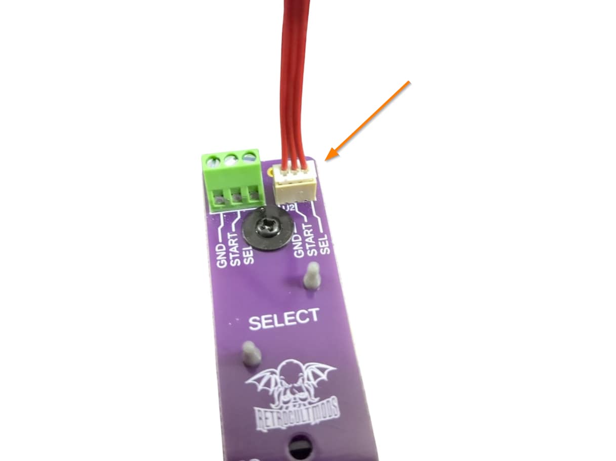
- Secure the new Start/Select board in the place of the stock Start/Select board, positioned with the white connector closest to the Strumboard. The original screws will likely be too small to cover the slots of the new board, so the provided screws can be used instead.
- Connect one end of the Red Wire into the white connector on the new Start/Select board.
- Connect the other end of the Red Wire into the white ST/SEL connector on the Strumboard.
Installing the Revival Kit Fretboard
Now its time to install the new RGB Mechanical Fretboard.
Gather the Revival Kit Fretboard, Translucent Frets, 3 White Wires, and 2 Long Screws.
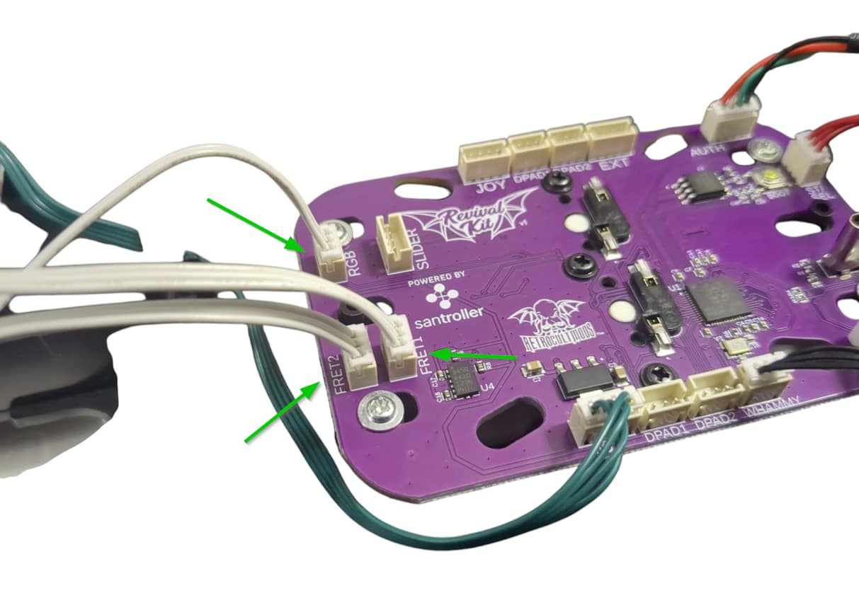
- Connect one end of each of the White Wires into the RGB, FRET1, and FRET2 connectors on the Fretboard. Connect the other end of each White Wire to the corresponding RGB, FRET1, and FRET2 connectors on the Strumboard. I recommend doing one wire at a time to prevent mixing them up.
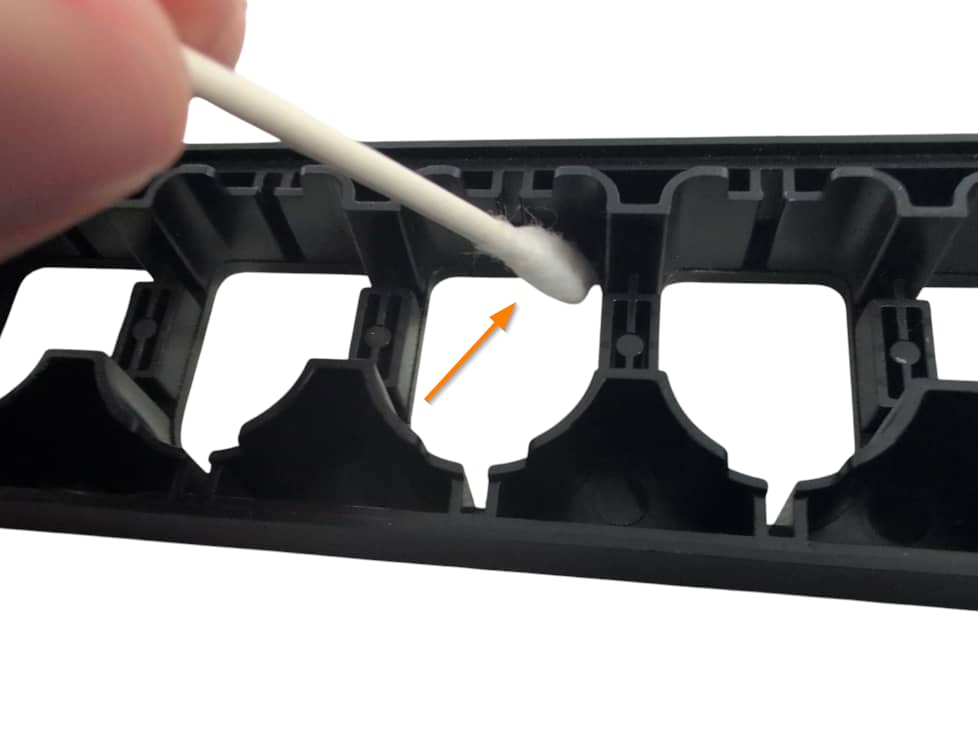
- Remove the stock silicone pad and frets if they are still in the fret slots. Wipe the inside of the fret slots clean if they are dirty. Then apply a small amount of lubricant to your finger or a qtip and lightly coat the inside of the fret slots with lubricant. Make sure to wipe away any excess lubricant that my have spilled to the front of the neck shell!
- Insert the new Translucent Frets into the fret slots.
- Place the new Fretboard onto the screw standoffs that the stock fretboard used to sit on (the red switches and white connectors should be facing down towards the Translucent Frets. Use 2 Long Screws to secure the new Fretboard.
- Route the White Wires through the neck and down through the body. Make sure they are clear of any screw standoffs so they are not damaged when reinstalling the neck shell.
Installing the detachable USB-C port
Next we will install the detachable USB-C port.
- Gather the top and bottom half of the port cover, the USB-C port board, two long screws, and the yellow wire. The port cover halves will be connected together; twist them in opposite directions to separate them. The small connecting plastic bits will not be visible from the outside of the guitar.
- Seat the USB-C port board into the bottom port cover, using the small pegs on the port cover to line everything up.
- Plug the yellow wire into the USB-C port board, then feed the other end of the wire through the hole on the top port cover.
- Line up the top and bottom port cover using the teeth on the bottom cover and slots on the top cover. Push the bottom cover forward so it lines up flush with the top cover.
- Press down on the top and bottom cover; you should hear a snap to indicate they are successfully assembled.
- Line up the assembled USB-C port with the screw standoffs that the on/off switch used to sit on. Use two long screws to secure the assembled USB-C port in place.
- Plug the other end of the yellow wire into the white connector on the Zeroboard labelled USB.
Installing the new Whammy assembly
Installing the Authentication cable
Installing the Authentication cable is quick and easy.
- Remove the two screws on the battery board, then remove the battery board with the two metal battery contacts.
- On the opposite body shell, find the two battery supports for the board we just removed. Press on one side of the support until it snaps off. Do this for both supports.
- Gather the Authentication cable.
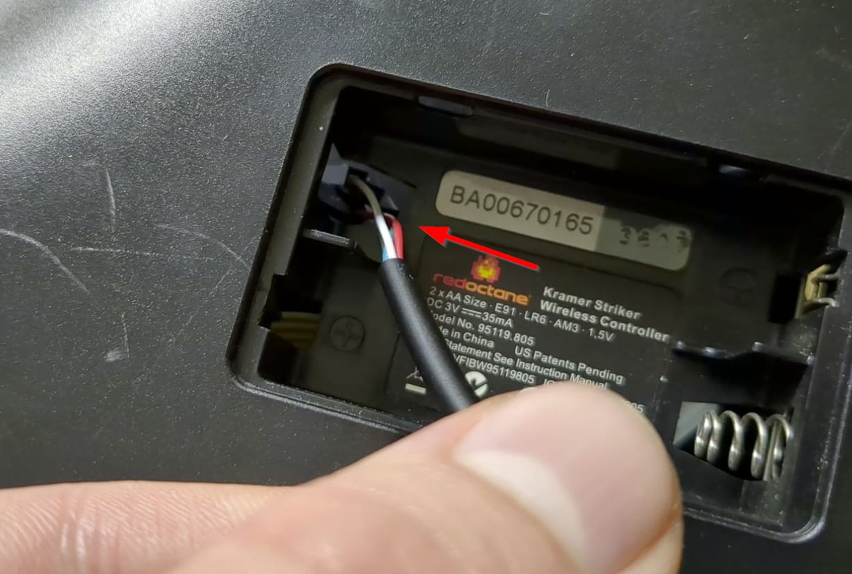
- Route the Authentication cable through the slot that the Wii extension cable used to route through.
- Plug the white connector end of the Authentication cable into the white connector on the Strumboard labelled AUTH.
Finishing Up
You’re almost done! Once you have ensured that each input works and that the tilt angle is where you want it to be, we can close up the guitar!
Make sure none of the wires are in the way of any plastic standoffs, as this will damage them when closing the shell. I would recommend taping down the wires to ensure they are out of the way.
With the front body and neck shell facing down, put the rear neck shell onto the front neck shell. You will need to apply pressure to close the shell. If you feel like part of the shell will not snap into place, open it up and double check that there is nothing blocking the standoffs. Repeat for the body shell.
After both sides are clamped down, install all of the screws you removed earlier:
- Rear neck shell - 8x T10 screws
Insert the neck shell into the body before screwing the body shell back together!
- Body shell - 13x T10 screws (remember the one under the Warranty sticker)
After everything is closed up, do not attempt to remove the neck from the body. If you think you may accidently do this in the future, I’d recommend putting some tape over the release lever on the back of the body to block it. Start playing!
Experiencing any issues? Reach out to me: support@RetroCultMods.com
